WIENER POWER ELECTRONICS CRATES
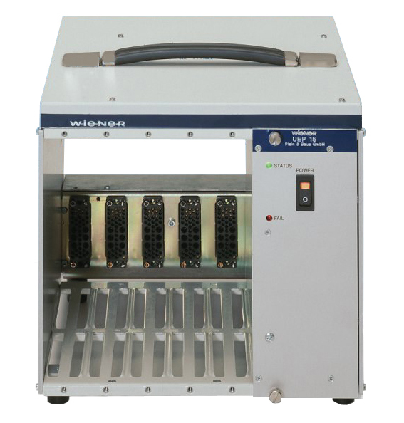
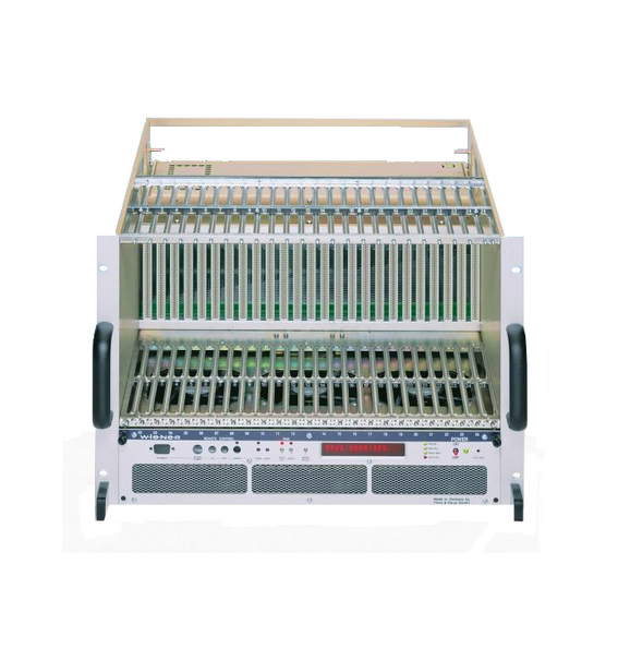
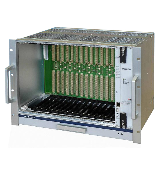
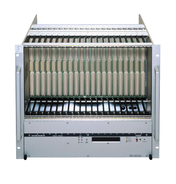
PHYSICAL Instruments offers you a wide range of NIM, VME64 / 64x, CAMAC, VXI, VXS, MicroTCA.4 crates, as well as LV / HV multichannel power supplies and microTCA.4 power supplies from our supplier WIENER Power Electronics. Please visit our supplier website for more details.
IF YOU CANNOT FIND YOUR REFERENCE, PLEASE CONTACT US
INTERNATIONAL STANDARDS: CRATES AND MODULES
The chassis architecture from WIENER Power electronics
Our robust and reliable crates from WIENER Power Electronics offer great configuration flexibility, ease of use and quick maintenance thanks to their modularity around 3 main elements:
- The ‘Bin’ is the central mechanical part supporting the electronic modules. It is very solid, made of a structure made of aluminium and rigid steel, with thick side walls that allow an excellent support of the fixed and removable elements.
- The power supply provides all power to the instrumentation modules. It is an important part of the chassis. The company WIENER Power Electronics is very demanding on this point. It offers a very reliable linear or switching technology, with a very low noise level which is in adequacy with the constraints required by the analog and digital acquisition modules.
- The fan tray provides superior cooling compared to a conventional ventilation system thanks to its unique design that compresses the air flow. It is microprocessor-controlled and guarantees reliable diagnosis and monitoring of the modules. It also provides a monitoring of the temperature in the bin and a monitoring of the voltages, currents and powers delivered to the modules. To supervise all these points, the fan tray offers control in local mode via a display and a navigation menu but also in remote mode via RS232, CAN-bus, USB and Ethernet interfaces.
NIM CRATES FROM WIENER POWER Electronics
Flexibility:
The NIM crate is ideal for small setups that require a high degree of flexibility. Thanks to modern high-speed serial interfaces such as USB-2 or Ethernet, the NIM standard is experiencing a renaissance. It is versatile and equally suitable for high-resolution scanner applications, complex logic and synchronization functions, spectroscopy amplifiers or simply low and high-voltage power supplies.
Robustness :
The NIM crates that we offer meet different needs but all of them provide strong robustness and reliability. Some are designed to be easily transported from one place to another, others are suitable for large fixed installations. Others, with increased currents only on the +/- 6 V strings are perfectly suited for spectroscopy, or with increased currents only on the +/- 24 V strings are suitable for high voltage modules. Finally, a specific range corresponds to experiments with a limited budget.
As required by the NIM standard, all our NIM crates designed by WIENER Power Electronics are equipped with a linear technology power supply for excellent accuracy. However, we offer a model with a switched-mode power supply to meet very high power requirements for which linear technology is not suitable.
CAMAC CRATES
CAMAC – “Computer Aided Measurement And Control” is a joint specification of the U.S. NIM and the European ESONE committees. CAMAC was introduced in 1969 by ESONE and fully defined in 1971 with the standards EUR4100 and EUR4600. It represents a complementation of the NIM standard for computer based experiment control and data acquisition / measurements.
Main field of CAMAC use are computer controlled control and data acquisition systems in nuclear and high energy physics experiments but also industrial applications in the past.
The electronic CAMAC modules have half of NIM width and are outfitted with a rear side 86-pin edge card connector. Module power, address bus, control bus and data bus are provided by the CAMAC Dataway which includes 48 digital data transfer lines (24 read, 24 write), strobe signal lines as well as address and control lines.
CAMAC crates for 19″ rack mounting have 25 slots. Station 25, the rightmost station, is reserved for a CAMAC Crates controller whereas slots 1 to 24 are normal stations.
Standard CAMAC crate controllers are double wide and use the two rightmost slots 24 and 25.
VME64 CRATES
VME is a high speed and high performance bus system with powerful interrupt management and multiprocessor capability. It was created by combining VERSAbus electrical specifications (1979) with the Eurocard format resulting in the VMEbus Revision A – 1981 specification. The VMEbus specification has since then been refined through revisons B (1982), C, C.1, IEC 821 & IEC297 and IEEE 1014-1987.
VME represents one of today’s most used industry bus standards (see VMEbus International Trade Association – VITA).
VERSAbus and consequently VMEbus were originally based on the MOTOROLA MC 680×0 architecture, i.e. it is a master-slave computer architecture with 32 bit wide address and data buses and it uses an asynchronous transfer principle. The VME64 extension doubles the transfer rate by simultaneously using both the 32 address and the 32 data lines multiplexed for 64 bit wide for data transfers (D64). Data transfer rates are up to 40 and 80 Mbyte/sec for D32 and D64, respectively.ANSI / VITA 1-1994.
The mechanical design is based on the Eurocard form factor. Standard VME modules are 6U high and 160mm deep. For phyics instrumentation a 9U x 400m form factor was added. All VME modules are equipped with two 3-row DIN-96 pin type connectors P1/P2 which match the backplane connectors J1/J2. VME crates have up to 21 slots and are equipped with the VME bus (backplane). Standard voltages provided by the crate power supply to the backplane are +5V and +/-12V, (5VSTBY).
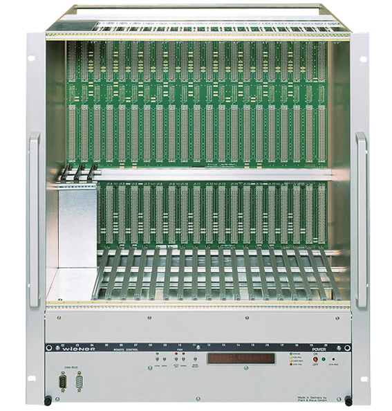
WIENER Power Electronics offers VME / VME64 crates in a compact design as VME mini crates or in full size with 21 slots for 19″ rack mounting with for both 6U and 9U VME bus cards.
VME64X CRATES
VME64x represents an extension of the VME64 Standard, VITA 1-1994 and became industry standard in 1996. It defines a set of features that can be added to VME and VME64 boards, backplanes and subracks.
The major new features of VME64x are expanded, 5-row P1/J1 and P2/J2 backplane connectors with 160 pins and an optional 95 pin 2 mm hard metric P0/J0 connector for more user defined I/O.
The 5-row connectors are backwards compatible to the 3-row VME/VME65 connectors. The additional pins are used for more signal ground returns, user defined I/O pins and geographical addressing.
Defining a 2-edge VME protocol bandwidths up to 160 MBytes/s can be achieved (2eVME). A synchronous data transfer can further boost it to 360Mbytes/s (2eSST).
VME64x defines with +3.3V and 48V additional power lines and increases the +5V power and ground capability per slot. Live insertion of modules is provided. Using the IEEE 1101.10 mechanical standard for the bin parts, card rails and front panels ESD / EMC protection is improved.
WIENER offers VME64x crates in a compact design as VME mini crates or in full size for 19″ rack mounting with 21 slots for both 6U and 9U cards. All crates are outfitted with IEEE1101.10 style mechanics and provide excellent EMC/ESD shielding.
VME430 CRATES
The CERN VME430 standard, often called “Nuclear VME”, is an extension of the VME64 Standard and was introduced in 1980 by the European High Energy Physics Laboratory CERN. It is fully backwards compatible to VME/VME64.
The VME430 specification adds 3-row / 30-pin DIN-type Paux/Jaux connectors which are located between the regular P1/J1 and P2/J2 connectors. Through these connectors the ECL voltages -5.2V and -2V as well as optionally +/-15V are provided to the VME430 modules. Further the Paux/Jaux connector adds additional ground pins, a serial bus and geographic addressing.
Considering the use of highly sensitive analog VME modules for nuclear and high energy physics detector read-out, the VME430 specification requests low noise power supplies.
WIENER Power Electronics offers VME430 crates in a compact design as 9 slot VME195-ECL mini crates or in 19″ rack mounting full size VME 6021/6023 with 21 slots for both 6U and 9U cards.
VXI CRATES
VXI – (VME eXtension for instrumentation): The demand for a compact, flexible and fast industry-standard instrument-on-a-card architecture has driven the development of the VXI standard. The modular form factor, high bandwidth, and commercial success of the VMEbus made it particularly attractive as an instrumentation platform. The tremendous popularity of GPIB also made it attractive as a model for device communication and instrument control protocols.
The VXIbus specification combines VMEbus with GPIB features and covers packaging requirements, electromagnetic compatibility, power distribution, cooling and air flow for VXIbus crate and plug-in modules. The new VXI-4 standard adds VME64x and VXS technology to the VXI architecture.
VXI crates/mainframes and modules come in 2 form factors – C-size (6U x 340mm) or D-size (9U x 340mm). VXI uses the full 32-bit VME architecture, but adds lines for instrumentation signals to the outer P2 connector rows (VME: user defined) and to the P3 connector of the D-size backplane.
Powered VXI mainframes for 19″ rack installation typically provide 13 slots. In order to be used for sensitive, analog test instrumentation VXI crate power supplies have lowest-noise requirements.
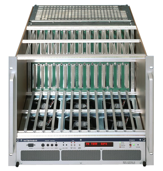
W-IE-NE-R offers both C-size and D-size VXI mainframes with high-power, ultra-low noise power supplies. All crates are modular designed, i.e. consist of the VXI bin, a plug-in fan tray as well as a UEP 6021 power supply which is plugged into the rear.
VXS CRATES
VXS – “VME-bus switched serial” is the new ANSI / VITA 41 standard which combines the 32-bit parallel VME-bus with high speed switched serial interconnect fabrics in order to increase the data transfer bandwidth to several GB/s.
VXS defines an interconnected network (fabric) of switched serial input and output ports with point-to-point connection with differential signals.
An active switching device manages data transfers from inputs to outputs. For VXS all active switching devices are located on a special switch card. Depending on the VXS backplane size and configuration one or two switch card slots may be used. All other modules that connect to the switch cards are called payload cards.
A VXS compliant crate can have one or two switch cards which have point-to-point connections to all payload cards. and allow all or a subset of the payload boards connected to it to intercommunicate.
A 19″ sub rack can hold a backplane with a maximum configuration of 18 payload slots and 2 switch slots. Backplanes with fewer payload or switch slots are allowed and can be configured in different topologies.
VXS also has increased allowed maximum currents for the 96 pin & 160 pin DIN/IEC connectors from the original 1A to 2A per pin. This allows higher crate power supply currents, and consequently higher power dissipation on the VXS boards which will be needed to fully utilize the high performance switch fabric capabilities.
This requires a better-designed crate with improved ventilation that can adequately cool the higher power VXS boards. All WIENER VXS crates can provide maximum DC power and are outfitted with high efficiency temperature controlled and monitored cooling fans.
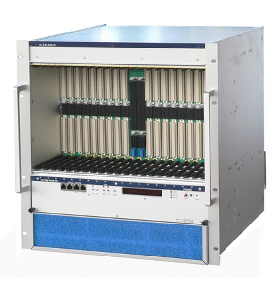
WIENER Power Electronics offers full size VXS crates with a 21 slot backplane (dual star topology, 2 switch, 18 payload, 1 legacy VME64x slot).
MICROTCA CRATES
The microTCA crate standard “Micro Telecommunications Computing Architecture” is an embedded, flexible and robust architecture. It is designed as a complementary structure to the ATCA standard ” Advanced Telecommunications Computing Architecture ” well known in the telecoms world. It combines a large bandwidth based on multi-Gb Ethernet serial interfaces. Its modularity, its extreme data processing power and its high reliability have given rise to interest in other fields. This is the case for the military, industrial control, avionics, accelerator physics and even data acquisition. The first microTCA specifications as “open standard” were written in 2006 by the “PCI Indutrial Computer Manufacturer Group” (PICMG).
COMPOSITION OF A MICROTCA CRATES
A microTCA crate system consists of several stages or “shelves”. Each stage includes several “carrier” racks. Each carrier integrates up to 12 Advanced Mezzanine Cards. All these assemblies are interconnected. In addition to these different blocks, there are redundant or shared power modules. There are one or two cooling units also in redundancy. There are the mechanical resources (subrack, backplane, board alignment guides, EMC / ESD interfaces, etc) to maintain them and make them functional. The whole system is controlled by electronic management systems called “Shelf Manager” and “Carrier Manager”.
AMC cards
- AMC cards are the main components of a microTCA crate. They provide various and useful functions. Among these mezzanine boards we find processor-based boards (CPU, FPGA, etc.) performing complex calculation and task processing functions. We also find signal processing boards (DSP), analog-to-digital conversion boards (ADC), memory boards for data storage. There are also boards for managing electronic input/output (I/O) signals, optical link boards, etc. The microTCA standard supports several mechanical sizes of AMC cards. From single height / single width to double height / double width. For example, one double width AMC format can be replaced by 2 single width AMC formats with the same Form Factor. The AMC cards have a Module Management Controller (MMC).
Power modules
- The power modules are mains powered and deliver DC voltages to the AMC cards. The microTCA standard specifies a payload voltage of +12 VDC to provide the necessary power for the AMC boards. It defines a voltage of + 3.3 V for distributed power management. This management is ensured by a logic that sequences, supervises and protects the electronic functions of the AMC cards. The power modules are equipped with intelligence capable of detecting whether an AMC card is newly inserted or removed. This mode is called “hot-swap” and to do so, the power modules have a management controller called Enhanced Module Management Controller (EMMC). The power modules themselves are hot-swappable.
The Fan Tray
- Fan tray cooling units are essential for extracting heat build-up from AMC boards. They are equipped with on-board intelligence and deliver variable air flows thanks to fans whose speeds adapt to the heat to be dissipated. As with the power modules, the cooling units are equipped with an EMMC controller and operate in “hot-swap” mode.
MICROTCA.4 POWER SUPPLY
The MicroTCA.0 standard, which defines the form factor of AMC boards, is classified according to 2 main dimensions. The width and the height. Indeed, a module can be of simple width and then occupies 1 slot (74 mm). A double-width module occupies 2 slots by removing a card guide (150 mm). Similarly a single module height is about 74 mm. A double module height is 150 mm. The depth is standardised at about 181 mm.
Originally, the MicroTCA.0 standard (basic specification for microarchitectures of ATCA types) brought together the elements that make up a MicroTCA system. Its backplane, power supply and power output, type of ventilation, control mode, etc. are all part of the MicroTCA system.
MicroTCA .4 is an extension of MicroTCA.0. The main feature is to offer a rear transition cage used for analog and digital I/O boards. This provides a more accurate management platform. This new specification is called MicroRTM ”Micro Rear Transition Module”. It responds to a demand from the physics community in the field of particle accelerators.
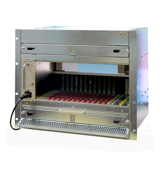
The Wiener MicroTCA.4 power module is a low noise and very high power density module (1000 W). It has a double width – double height form factor that also meets the microTCA.0 standard. It is capable of supplying electrical power to 12 Advanced Mezzanine Cards, 2 fan units and 2 MicroTCA Carrier Hub MCH controller modules.
INTERCONNECTIONS BETWEEN MODULES
In this diagram, the main infrastructure that manages the interconnections between the AMC modules, power modules and fan units is called the MicroTCA Carrier Hub (MCH). This is equipped with a MicroTCA Carrier Management Controller (MCMC) with an interface called the Intelligent Platform Management Bus (IPMI). This consists of the IPMB-L and IMPB-0 buses (geographic addressing bus, clock, etc.). The IPMB-L bus provides communication between the HCM and the AMC boards, the IMPB-0 bus provides the link between the HCM, the power modules and the fan units.
Since the HCMs represent a crucial point in a Micro TCA system – where any failure could block the whole system – it is possible to duplicate it. This is made possible by a redundant configuration comprising a pair of HCMs. Its mechanical format is identical to that of an AMC card.
The other elements that make up a microTCA system: https://www.picmg.org/openstandards/microtca/
Based on its experience in power electronics, the company WIENER Power Electronics, has developed a microTCA.4 power module for microTCA crate https://www.picmg.org/spec-product/1000w-mtca-4-power-supply/.
WIENER Power Electronics is a member of the PICMG group.

